

By Parth Bosmia
Thermowells are critical yet often overlooked components. Serving as protective enclosures for temperature sensors, such as resistance temperature detector (RTD) and thermocouples, thermowells ensure accurate readings while shielding sensors from the harsh process environment. However, poor design or misapplication can lead to catastrophic failures, including toxic releases, fire hazards, and equipment damage.
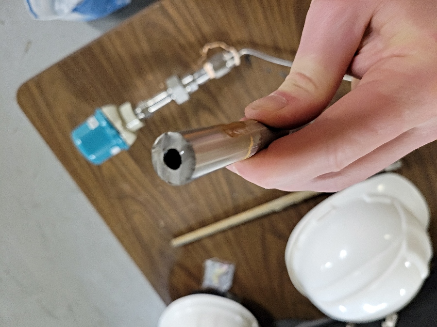
A thermowell is a cylindrical, sealed tube that extends into a process stream and houses a temperature sensor. This isolation allows the sensor to be removed or replaced without disturbing the process or requiring depressurization. Typically installed in piping systems, tanks, or reactors, thermowells ensure the longevity and integrity of temperature measurement devices.
Thermowells are primarily used in anaerobic sludge digestion during the wastewater treatment process. Anaerobic digestion is a biological process where microorganisms break down organic matter in the absence of oxygen, producing biogas and a nutrient-rich digestate. This process is highly sensitive to temperature fluctuations, and the digester’s contents are corrosive and abrasive. Thermowells protect temperature sensors from the corrosive and abrasive environment inside the digester tanks.
Subscribe to our Newsletter!
The latest environmental engineering news direct to your inbox. You can unsubscribe at any time.
Sometimes, chemical injection quills are used, and they behave like thermowells. If the proper calculation is not performed, the quills will likely be lost/fail inside the pipe.
Additionally, the condenser cooling water application, a type of industrial water usage, has a water velocity sufficiently high to damage the thermowells. Consequently, thermowell calculations must be performed before selecting the type and material of the thermowell.
The failure of a thermowell is not just an instrumentation issue, it is a process safety hazard. Potential consequences include:
Safety hazard: a rupture may result in fire, explosion, or toxic chemical release.
Environmental risks: process fluid leakage into the environment.
Process disruption: shutdowns due to inaccurate readings or sensor damage.
Material damage: high-pressure fluid jets can erode nearby equipment
Loss of life: particularly in high-temperature or hazardous fluid applications.
A well-known case of design oversight occurred at Japan’s Monju Nuclear Power Plant in 1995. A sodium leak caused by a thermowell failure led to a plant shutdown that lasted over 15 years.
Thermowells are available in a variety of materials tailored to the process environment. Material compatibility is essential for long-term performance. In corrosive or high-temperature systems, upgrading material selection can prevent early failure.
When fluid flows across the thermowell, vortex shedding occurs behind the stem. If the frequency of these vortices matches the natural frequency of the thermowell, resonance occurs. This can lead to vibrations that can cause fatigue failure.
When doing design calculations, it is important to gather input parameters, such as process temperature and pressure, fluid density, viscosity and velocity, thermowell dimensions and the elasticity and density of materials.
Best practices for installation
- The tip of the thermowell should face the flow direction (especially in elbows or bends)
- Ensure test well accessibility for sensor maintenance
- Maintain minimum clearance of 100 mm from insulation and structure.
- Avoid proximity to obstructions (valves, tees) that can disrupt the flow profile.
Limitations and design oversights
The use of computational fluid dynamics and finite element analysis for critical applications is important. Even with adherence to standards, common design flaws occur. These include:
- Oversizing, which increases drag and lowers natural frequency
- Undersizing, which reduces strength and increases vibration risk
- Ignoring insulation thickness, which leads to incorrect U-length and wake frequency ratio.
Conclusion
Thermowells may seem like simple devices, but their failure can have severe consequences for personnel, the environment, and plant operations. A robust thermowell design involves not only selecting the right material and dimensions but also performing thorough wake frequency analysis in line with ASME standards.
By understanding the mechanics behind vortex shedding, taper ratios, and U-length, engineers can ensure safe and reliable temperature measurement across all process conditions.
Parth Bosmia is with R.V. Anderson Associates Ltd.
Email: pbosmia@rvanderson.com
This article appeared in the October 2025 edition of Envionmental Science & Engineering Magazine.